
A Jacket, Microcontrollers, and Clojure
》I ♡ Cyberpunk
If the look of this blog is not a clue already, let me just go ahead and say I love cyberpunk. And maybe plain old punk just a little bit, too.
I love going to Alchemy, or To The Moon. I’m frequently at the Atlanta Eagle. Sometimes you can even spot me at a goth night event. I already have cyberpunk-adjacent clothing and boots. OK, that’s a lie, the boots are straight-up cyberpunk.
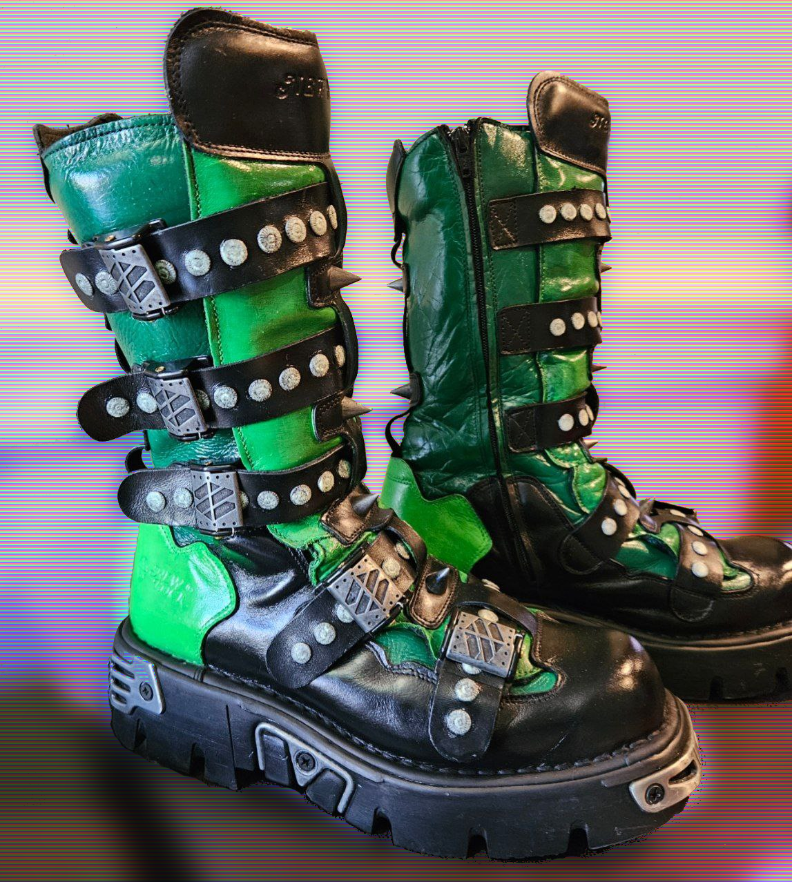
So why not have more lovely cyberpunk gear? In leather, of course. I just happen to have an old leather jacket that needs some love.
But if this jacket is going to be cyberpunk it needs some glow. It needs some radios. Maybe input devices. Definitely LEDs.
Here’s the story of building the first component for the jacket.
》Limiting Myself Only At The Sky
There is an old leather biker-style jacket in my basement. The original idea was to paint the back of it with a version of the Cthulhu-qua-circuit board I had made into stickers awhile back. From there the idea of adding some lights was just obvious.
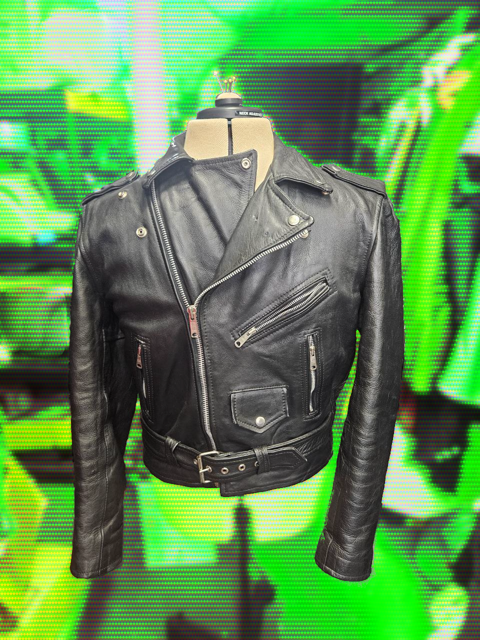
Of course the ideas got out of hand. Inspiration was sought. Electronics bits were purchased and played with. Finally a plan emerged:
Electroluminescent panels on the wrist-end of the sleeves
A flexible display on one arm
A series of M5Stack Atom Matrix displays on the other
Software-defined-radio (
SDR) antennaAn interactive "badge" screen on the front
Bend sensors embedded at the armpits and elbows
A Raspberry Pi 4 brain to tie it all together, mounted on the shoulder
I am also planning a hacker wristwatch, inspired by FUBARprops, that can be worn alone or integrated with the jacket.
Then this will need quite a bit of software to tie it all together. Maybe it
can read and display interesting signals the SDR finds. Maybe it can
collect WiFi packets like a Pwnagotchi. Maybe it
can pop open Tesla gas tank caps when I walk by :D Whatever it does, I
want it to be fun and interactive.
》But Then Comes Reality
》Bitten By Bluetooth
First up was the arm display. I picked up an 8x16 flexible LED display that
uses Bluetooth Low Energy for communication. It pairs with the CoolLEDX app
for control, which is easy. But that’s not programmable. Pulling out a phone
to change the display manually would destroy the fun. Having the display react
automatically as events happen would be so much better. So I needed another
way to drive it.
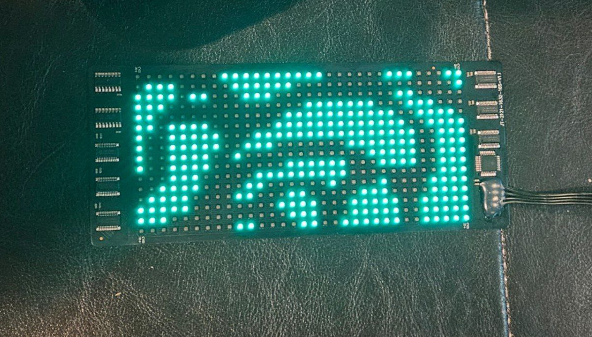
Some searching revealed UpDryTwist/coolledx-driver which worked, but also is written in Python and I’d much rather be doing all this coding in Clojure. So I tried and found out that the device really doesn’t follow BLE standards. It expects raw data to be pushed to an unidentified GATT service. I made some progress on re-implementing the driver, but reverese engineering the data format even with the Python code as a guide was slow progress.
Even worse, the BLE communication is slow. The display actually shows a brief "loading" animation for each image pushed to it. If there was nothing better this would just have to suffice. I’m glad there is a better option.
Maybe I’ll put up a post later about what I learned while trying to make BLE work with Clojure.
》WS2812 & A Microcontroller
A friend challenged me to try skipping the Bluetooth part entirely and use a microcontroller to drive the LED panel. I had worked with Arduinos, ESP8266s, and ESP32s in the past — ask me about Atelier Chakraspace sometime — and kind of dreaded trying again. That’s because many of these panels are WS2812 based, which means the data logic lines for the LEDs want 5v but most of the microcontrollers put out 3.3v. Yeah yeah yeah, that can be handled with logic level converters, but once other components like that have to be added in the project becomes much more complex. I tried to get circuit boards fabricated for the Atelier Chakraspace project, and those failed spectacularly. Four years later and that project is still not a reality, and all due to the extra complexity.
With a bit of resignation, I tried again:
A 16x16 LED panel
A Pro Micro ATmega32U4 microcontroller
A Raspberry Pi 4
PlatformIO and FastLED
Clojure
The ATMega was chosen because it has 5v data lines … or so I think. The specs I read were not completely clear. Anyway, it was cheap enough to give it a try and worked well in the end.
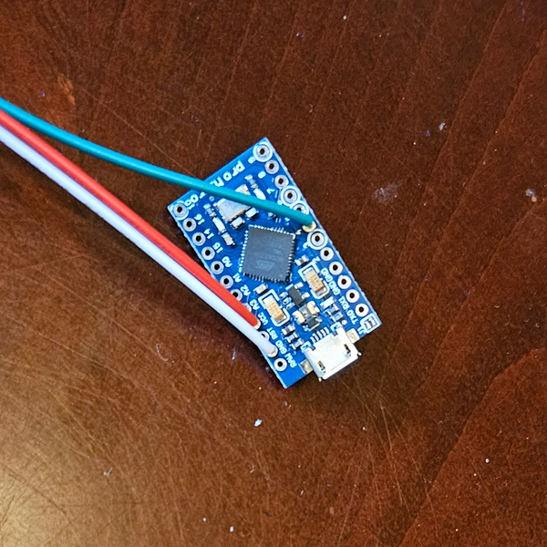
PlatformIO was my choice for programming the microcontroller. It is a little bit confusing to get going, though once set up is less constraining than using the Aruino IDE. The examples for starting a new project based on the ATMega32U4 were enough to make it work. For driving the WS2812 LEDs there are ample examples of how to use FastLED.
Less than half an hour of work and there was a single LED lit on the matrix!
A little more coding and the display was lighting up one LED at a time in a simple animation. A sort of "tracer". Which demonstrated up a fresh problem: the matrix is essentially a WS2812 LED strand that has been "woven" back and forth, thus every other row of the display is reversed. That will have to be handled in code before it can display images.
# "tracer" code

#include <Arduino.h>
#include "FastLED.h"
#define NUM_LEDS 256
#define DATA_PIN 4

CRGB leds[NUM_LEDS];

leds[x] = CRGB::Green;
if (x == 0) { leds[NUM_LEDS - 1] = CRGB::Black; }
       else {leds[x - 1] = CRGB::Black;};
x++;
if (x >= NUM_LEDS) { x = 0 ; };
FastLED.show();
With that, I was pretty confident the panel would work. So next up was to give some attention to the "brain" of the jacket.
》A Pi & Serial Data
Driving displays, reading SDR, and coordinating actions is easier if the jacket has a central brain. The Pi 4 was chosen for a balance between capability and power consumption. Since this will have to run on battery, it needs to be somewhat efficient. Yet the rest of the capabilities like SDR require more power. Who knows if this will work? I’ve used the DevTerm for hours on two vape batteries. Surely I can make this work at least that long, even if it requires a few more batteries? There is plenty of place to hide them in that jacket!
When the microcontroller is plugged in via USB it shows up as the /dev/ttyAMC0
device. Sending data should be as easy as writing to that file. "Should be." To
find out, I updated the C++ code to allow setting the brightness of the chaser LED.
void loop() {

  if (Serial.available() > 0){
    char command = Serial.read();
    switch (command) {

      case 'b': {
            Serial.print("Changing brightness: ");
            brightness = Serial.read();
            FastLED.setBrightness(brightness);
            Serial.println(brightness);
          };
          break;
    }
  }
And then tested with a simple echo statement from bash.
# -e here causes echo to interpret \x0a as a byte, in this case '10'
echo -e b\\x0a > /dev/ttyACM0
Success! That was enough to give me hope the display would work.
》Code Frenzy
》Unchecking The Bytes
One of the main use cases for this LED matrix is to display "idle animations" as well as other information as it is gleaned from the environment. No matter how all those plans play out, the bare minimum I need is to push image "frames" to the matrix.
But first, can Clojure sanely talk to the serial port? Trying to change the brightness should be a good test.
Here is the code, along with lines executed in-REPL in the comment block:
;in the namespace declaratation
(:require [clojure.java.io :as io])

(defn set-brightness [brightness]
  (with-open [w (clojure.java.io/output-stream "/dev/ttyACM0")]
      (.write w (byte-array [(int \b) (byte brightness)]))))

(comment
  (set-brightness 10)  ;great!
  (set-brightness 200) ;uh-oh "Value out of range for byte: 200"
)
It turns out there are some issues with writing bytes to an output stream with
Java (and therefore Clojure). The C++ code is using unsigned integers - with an
8-bit int ranging from 0 to 255. Java, however, only has signed ints. Which
means the numbers are stored using
Two’s Complement
so that negative numbers can be represented. Now the range of ints is -128 to
127.
Clojure handles this with unchecked-byte which gives us the proper behavior:
;in the namespace declaration
(:require [clojure.java.io :as io])

(defn set-brightness [brightness]
  (with-open [w (clojure.java.io/output-stream "/dev/ttyACM0")]
      (.write w (byte-array [(int \b) (unchecked-byte brightness)]))))

(comment
  (set-brightness 10)  ;it's dim!
  (set-brightness 200) ;it's very bright!
)
》Streaming The Bytes
Now it’s time to push an image to the matrix. FastLED stores them as an array of CRGB structs, which are basically three 8-bit unsigned integers in a row. The nice thing about that is the bytes can be streamed over the serial port and read directly into the array! Here is an added "command" extending the switch statement from before that loads the LED array. Note that the number of LEDs is multiplied by three to accommodate the R, G, and B bytes.
case 'i': {
  Serial.println("Uploading image");
  Serial.readBytes((char*)leds, NUM_LEDS * 3);
}
break;
Now the Clojure code just has to push the right set of bytes over the output stream and we’ll have control over the image on the matrix!
In my Going places I shouldn’t with JNA post, I cover useful Java classes for dealing with images. That was a great foundation for what had to be done next.
The plan of attack is to load an image with javax.imageio.ImageIO/read,
convert it into TYPE_INT_RGB by creating an empty "working image" of
that type and then using .drawImage to copy the loaded image into
the working image. After that, the pixel array for the image can
be found by pushing it through .getRaster, .getDataBuffer, and
then .getData.
;in the namespace declaration:
  (:import [javax.imageio ImageIO]
           [java.awt.image BufferedImage]
           [java.awt Color]
           [java.io DataOutputStream ByteArrayOutputStream])

(def matrix-width 16)
(def matrix-height 16)
(def working-img (new BufferedImage matrix-width matrix-height BufferedImage/TYPE_INT_RGB))

(defn load-image [imgpath]
  (let [img        (ImageIO/read (io/file imgpath))]
    (.drawImage (.getGraphics working-img) img, 0, 0, nil )))

(defn push-image-raw [imgpath]
  (let [img        (ImageIO/read (io/file imgpath))
        _          (.drawImage (.getGraphics working-img) img, 0, 0, nil )
        pixelarray (-> working-img .getRaster .getDataBuffer .getData)]
    (with-open [w (io/output-stream "/dev/ttyACM0")]
      (.write w (int \i))
      (.write w (byte-array pixelarray)))))

(comment
  (push-image-raw "avatar.png") ; disaster!
)
Sadly, that turns out to be a disaster.
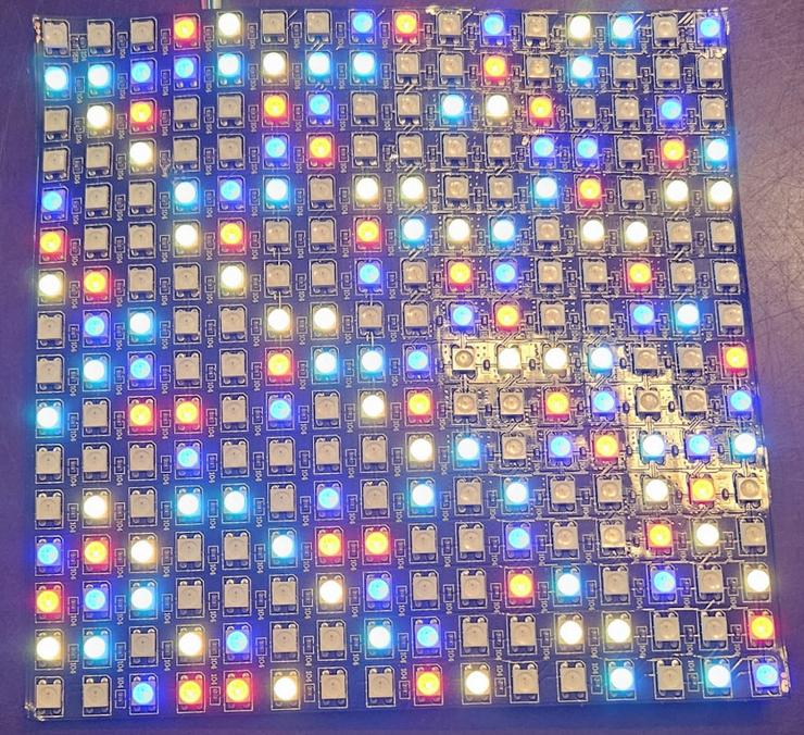
》Fixing The Bytes
That of course makes sense - the internal representation of the BufferedImage
is a Java integer which is larger than the 8-bit ints that FastLED uses. And
FastLED uses three uint8_t bytes in a row. That means each int has to be
unpacked into three bytes. You can find many guides on the internet for this,
but the idea is pretty simple: use a bitmask to mask off the portion of the
integer to keep, then shift it right to "cut off" the parts you don’t need. If
that doesn’t make sense, don’t worry. Here’s the code:
(defn to-rgb [pixel_int]
  (let [b (bit-and 0x000000ff pixel_int)
        g (bit-shift-right (bit-and 0x0000ff00 pixel_int )  8)
        r (bit-shift-right (bit-and 0x00ff0000 pixel_int ) 16)]
    [r g b]))
Now that just needs to be mapped over the pixel ints and flattened before
sending down the wire:
(defn push-image [imgpath]
  (let [img        (ImageIO/read (io/file imgpath))
        _          (.drawImage (.getGraphics working-img) img, 0, 0, nil)
        pixelarray (-> working-img .getRaster .getDataBuffer .getData)]
    (with-open [w (io/output-stream "/dev/ttyACM0")]
      (.write w (int \i))
      (.write w (byte-array (flatten (mapv to-rgb pixelarray )))))))

(comment
  (push-image-raw "rainbow.png") ; smaller disaster!
)
Better! But this was supposed to be a rainbow as a test of colors. I forgot to fix the "weave" pattern built in to the matrix. I also didn’t remember to turn off the tracer animation, so it ate away part of the image.
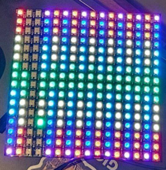
This was an easy, if not clever, fix. Just use map-indexed which is like map but also
passes the index number of the entry to the function being called. Then it runs reverse
on the even rows and finally flattens them back into a list.
(defn reorder-matrix [array size]
  (let [parted (partition size array)]
        (flatten (map-indexed (fn [i row] (if (even? i) (reverse row) row)) parted))))
With the final push-image function being:
(defn push-image [imgpath]
  (let [img       (ImageIO/read (io/file imgpath))
        _         (.drawImage (.getGraphics working-img) img, 0, 0, nil)
       pixelarray (-> working-img .getRaster .getDataBuffer .getData)]
    (with-open [w (io/output-stream "/dev/ttyACM0")]
       (.write w (int \i))
       (.write w (byte-array (flatten
                   (mapv to-rgb (flatten
                      (reorder-matrix pixelarray 16)))))))))
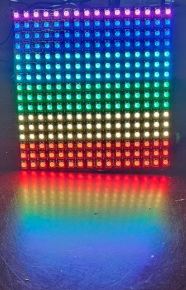
Finally, a proper image.
》Prototyping & Naming
With all that work done, I was eager to get a feel for how it would really look. The 3d printer produced a simple case with a VESA mount, which seems cheekily appropriate for the theme here. A little bit of tape held the Pi and the LED matrix in place long enough for some pictures:
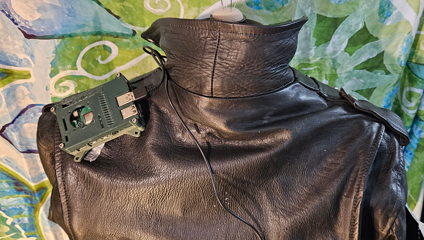
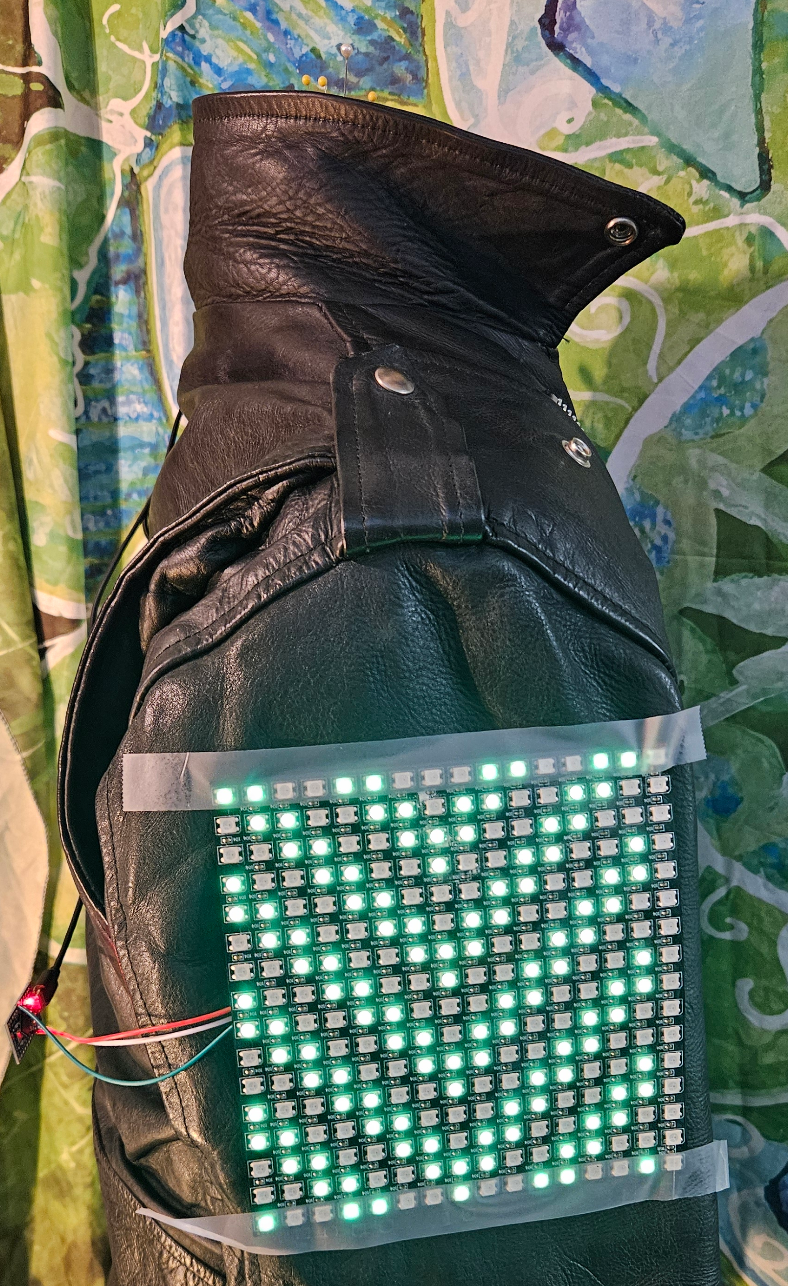
That’s a reasonable start. Once battery packs are tested and the SDR antenna is figured out the case will have to be re-designed to match. At that point any extra greebles, lights, and input devices can be incorporated. The LED matrix will need some covering and/or frame for protection.
Along the way I decided on a name for the project: P.E.P.R.
I’ll be putting together a P.E.P.R. Jacket page with a high-level plan while continuing to post details as it progresses.
